Newer posts
09.11.2017: Now processing GLONASS
I have mentioned the issues I've had getting PPP from the Novatel OEMV-3 receiver before. In the end, I ended up writing my own RINEX 2.11 converter (Range2RINEX, https://github.com/opronningen/GPS). The converter is not complete (notably it does not produce NAV-files, and it does not convert SBAS, L5 and L2C) but it does convert the values needed for processing the observations with PPP. I revisited the project this weekend, it now correctly (I think) converts GLONASS observables. For some reason, gLAB chokes on the resulting RINEX-files, but NrCAN PPP process them just fine - with marginally better results than what I get when converting using Novatel Convert. :)
My antenna is not strictly GLONASS capable, so the SNR of the observations are not great, but it does track a few satellites. I will keep logging for a while, and see how it pans out.
Next up, L2C. It might not require major changes, but I will need to re-read the RINEX 2.11 spec again. Probably more than once..
The receiver is also cabable of tracking L5, although that particular statement needs some qualification - there are 6 channels available for tracking L5; but the receiver does not automatically assign any satellites to these channels! In short, to track L5 one must manually assign SVs with L5 to these channels.. Which makes the capability rather limited. But since I already have a software process running on my lab-computer collecting the observations, it should be no big deal to extend this to find the 6 best SNR L5-cabable satellites (Block IIF) in view, and assign these to the L5 channels.
I am looking for an L1/L2/L5 GPS+GLONASS capable antenna at a reasonable cost, at which point I will update Range2Rinex to also handle L5 correctly. I do have an old choke-ring antenna I've never got around to putting up, I guess I can always hope the filters are wide enough to allow some L5 through..
Update 13.10.2017
By accident I discovered that I am able to track L5 on a few satellites at high altitude. Poor SNR, of course, but it did give me the required data to update Range2RINEX to support L5. It required a bit more work than I anticipated, I ended up rewriting most of it. The upshot is that it now converts L5, L2c and SBAS as well. I also implemented the required changes to NovLog, so that it now automatically assigns Block IIF satellites to the L5 channels.
29.10.2017: Frequency distribution in the lab
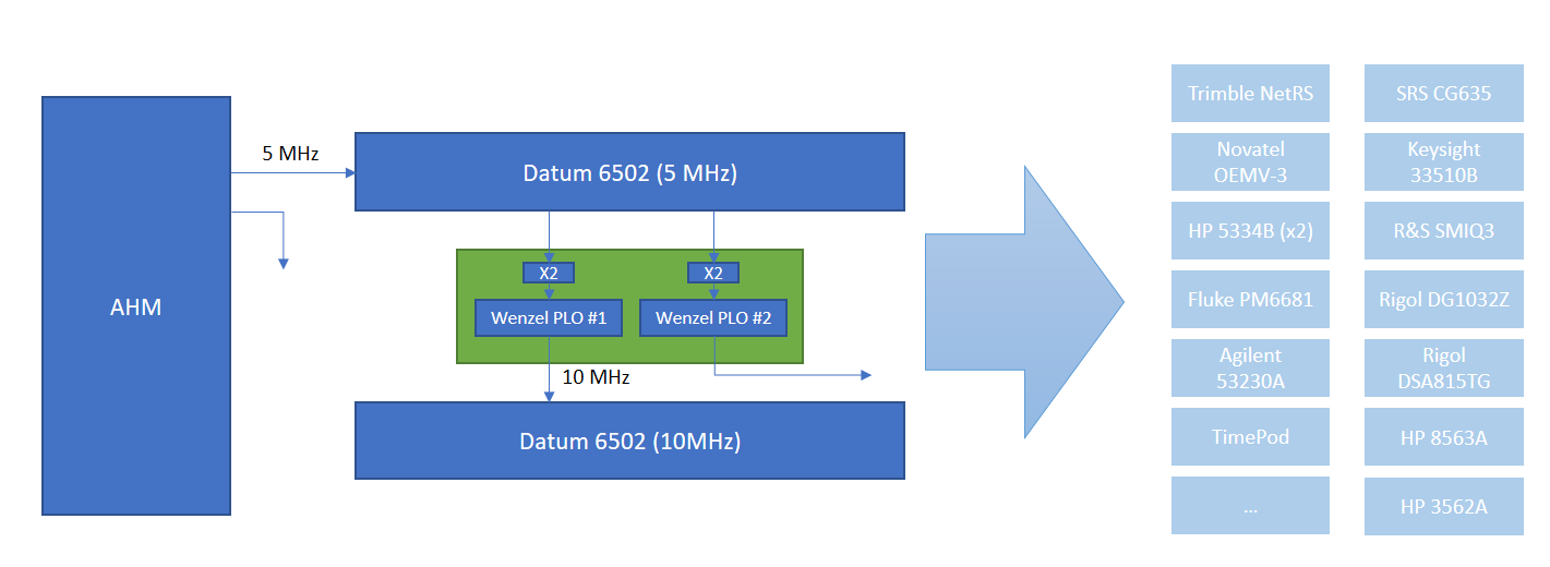
After considerable procrastination I completed a much needed overhaul of the frequency distribution in the lab. The aforementioned Wenzel PLO's were nicely boxed up in a heavy cast aluminum box (with independent frequency doublers), and a couple of Datum 6502B Distribution Amplifiers mounted. The DA's distribute 5MHz from the AHM, and 10MHz from one of the phase locked Wenzels respectively. The signals are used as references to my (too many) instruments of varying description and state of disrepair.
This setup leaves me the 10MHz from Wenzel PLO #2 available, as well as one 5 MHz from the AHM. The idea is to use two uncorrelated 10MHz signals as independent references to the TimePod. Since the signals are uncorrelated (outside the loop BW of the PLL), the phase noise of the references will cancel out in phase noise measurements. ADEV-measurements will not have this benefit, since ADEV is measured on the TimePod from only one of the references - but given that the reference is phase locked to the AHM, for most cases it should be good enough.
The additional 5MHz signal from the maser has poor phase noise, but it is not "contaminated" with the temperature-related phaseshifts observed on signals passing through the DA's and associated crows nest of cables. When I want to do really sensitive ADEV-measurements (below e-13 at tau > 10 seconds), I can use this signal as a reference. So I should be pretty well covered for both types of measurements.
I agonized over the powersupply to the Wenzels - in the end I opted for a MeanWell 18v external switching powersupply, dropped to 15v through two LM7815s. I expected to see some additional phase noise, but I could find no difference what so ever between this setup and powering the PLO's from a clean Rohde & Schwarz linear powersupply.
10.10.2017: A lesson in temperature sensitivity
My Hydrogen maser output is 5 MHz, and a few instruments in my lab requires a 10 MHz reference. As I've already mentioned elsewhere the phase noise of the AHM is also a bit degraded, so when a couple of 10 MHz phase locked oscillators from Wenzel (501-09815G) showed up on ebay for a reasonable price, I jumped at the chance and bought the pair. The phase noise is presumably quite good, and since it will be phase locked to the maser, I do not really care about the ADEV beyond 1 second or so. Anyway, as soon as I got the OCXO's, I wanted to make some measurements and see how they perform.
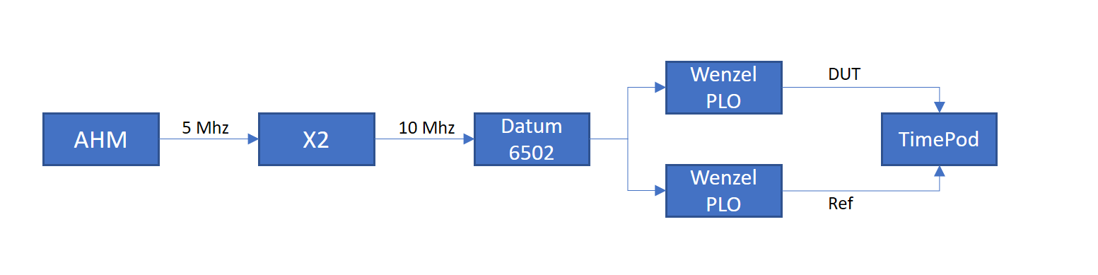
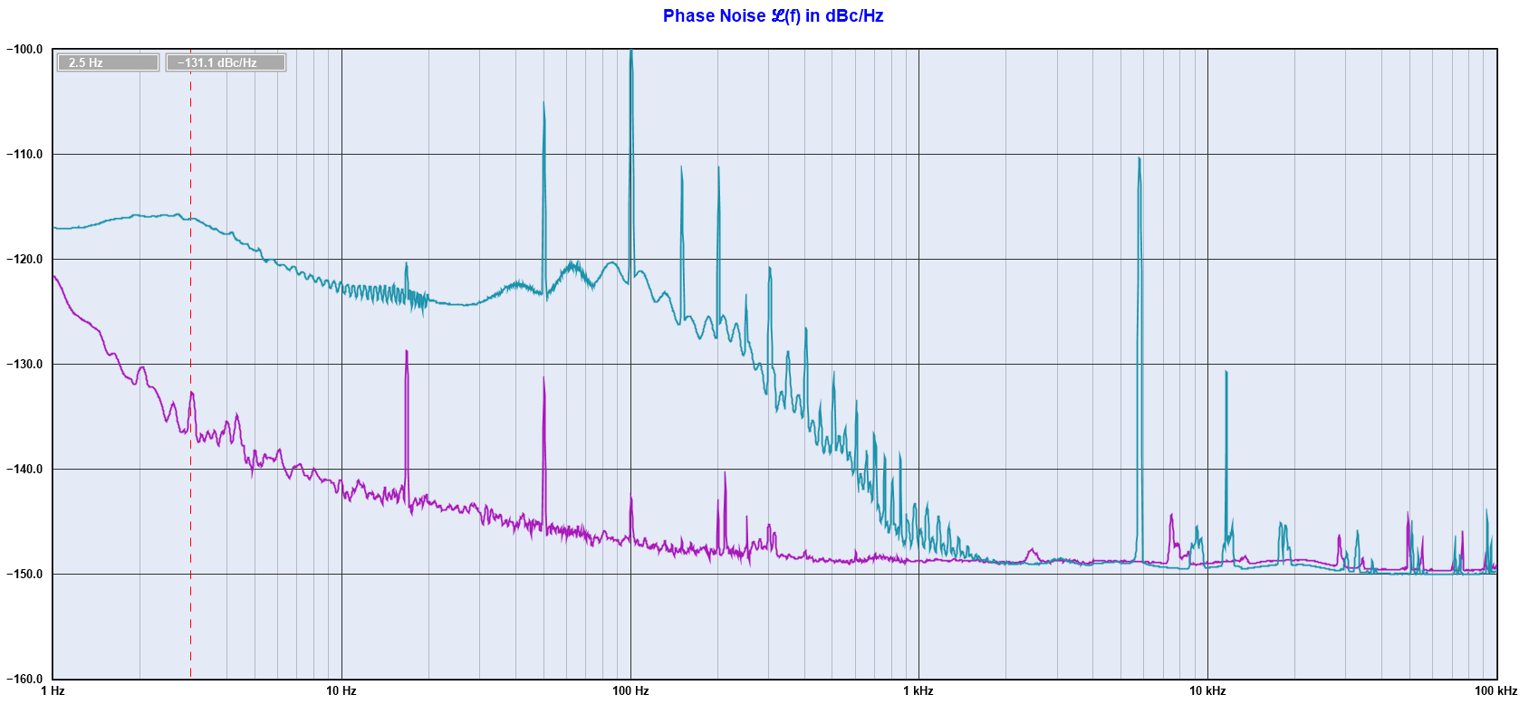
These PLO's lock to a 10 MHz source, the lack of which was the issue in the first place. However, since they will phase lock with a relatively long time constant, the 10 MHz reference does not need to be particularly clean. So I use a diode frequency dobler on the 5 MHz maser signal, and distribute the 10 MHz through a Datum 6502 distribution amplifier. The Wenzel inputs are taken from the DA, and the resulting clean 10MHz is taken as DUT and REF on my TimePod. The goal initially being to measure the phase noise - but I also measured ADEV.
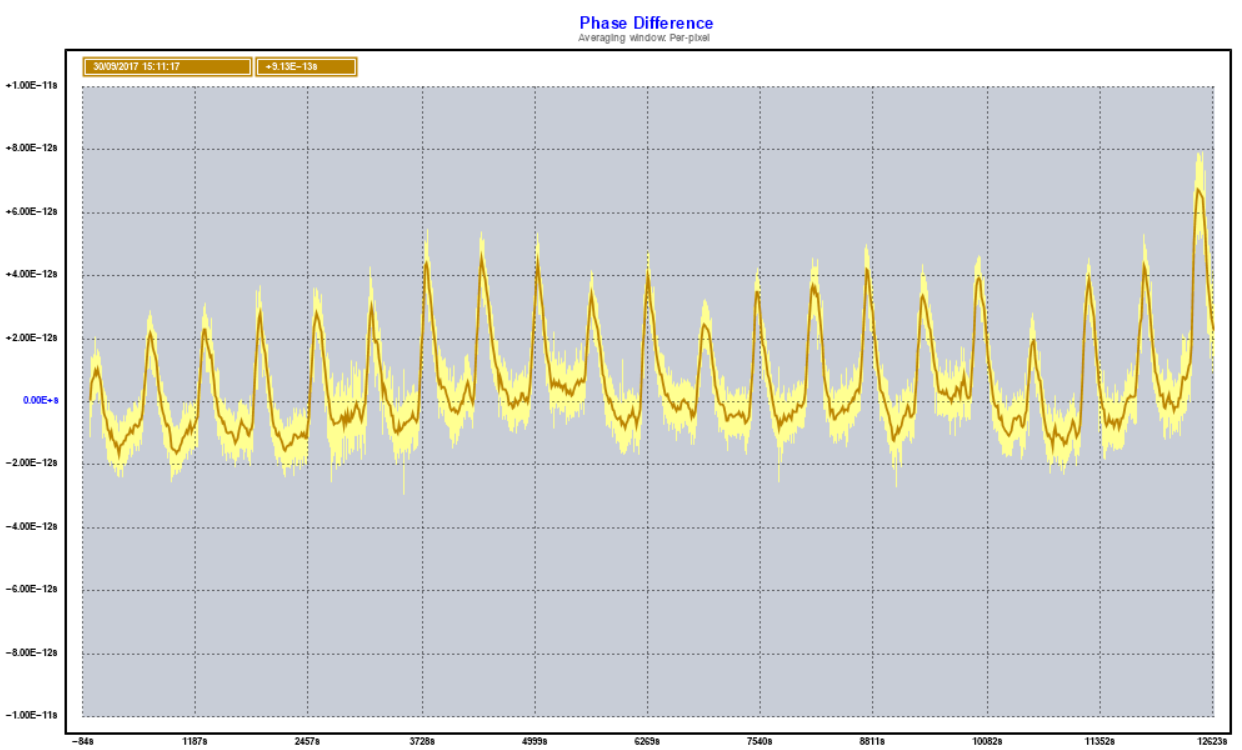
The aircon in my home shop is blowing air directly in the direction of the bench with the OCXO's, so I tried shielding the OCXO's with a box, and left it to settle in for a few days before running the measurements. I got some "wiggle" on the phase plot, but only a few picoseconds. The period matches my aircon cycling - but since there are several bits and pieces in between the maser and the OCXO's, it could be any number of things that shows picoseconds of phase drift; the OCXO's themselves, obviously, but also cables and connectors, the DA, the frequency doubler, the TimePod itself.. Hard to say.

But then I removed the shielding box mid measurement. The plot speaks for itself.. This will not come as news to most time-nuts, but I found it interesting just how much temperature can screw with even good quality OCXO's. The shielding was simply a plastic box placed up-side-down over the OCXO's, but the effect is undeniable.
It's worth thinking about what we're actually measuring here: both oscillators are locked to the same source, and are supposed to be equal in "every respect". If they both responded identically to the temperature shifts, we would see nothing on the plots - both the reference and the DUT would deviate by the same amount with respect to temperature, cancelling out. What we see is the difference between the two - which says nothing of the absolute temperature-dependant frequency shift of either oscillator.
As a side note, it is interesting that the phase plot seems to show "interference" of two slightly different temperature control loops, one in each OCXO.
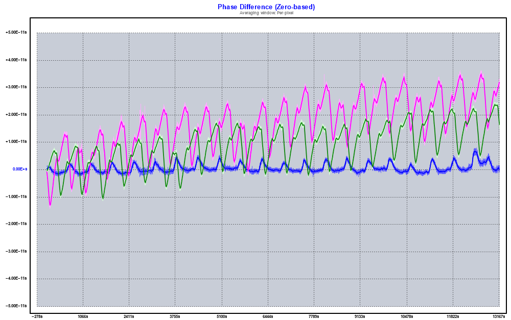
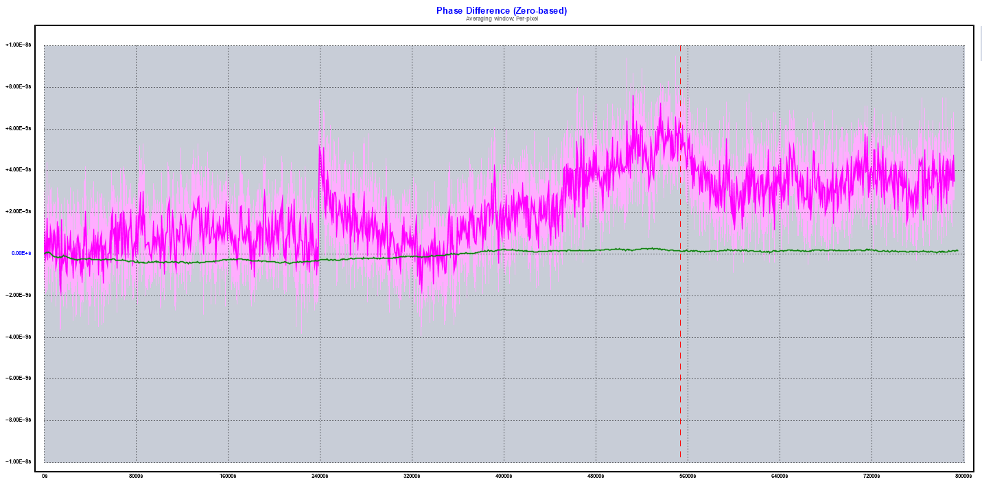
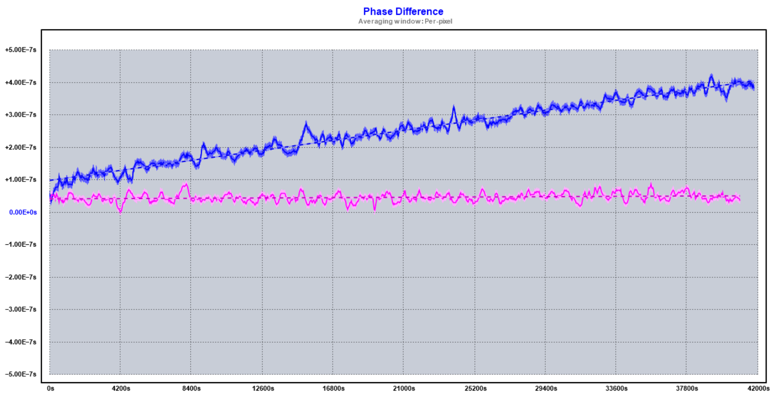
I also measured the absolute frequency-deviations of the OCXO's using the AHM as reference. (Blue is the difference between the two, pink is PLO #1, green is PLO #2) It looks to be of the order of 20ps peak to peak during an AC cycle. Clearly,these OCXO's needs to be mounted in a proper metal enclosure, and some care given to reducing the temperature variations. It is also interesting to note that there is a slight frequency offset, one or two parts in E-15. Let's just say I can live with that.. I struggle to maintain frequency accuracy of the maser better than about 2E-14, as calculated with PPP, so a few parts in E-15 is no big deal.
Still worth remembering if I ever try to measure residuals of a device using the PLO's as reference for the DUT, and AHM as reference for the TimePod.

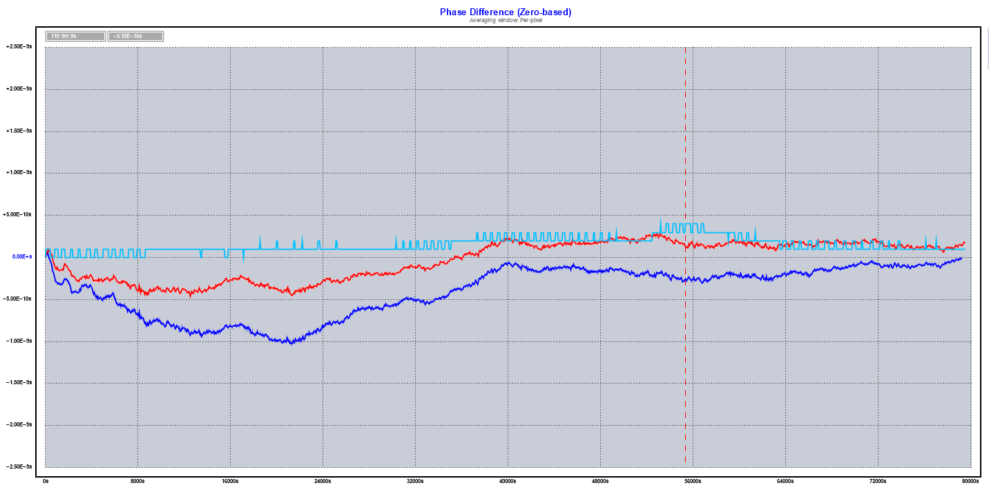
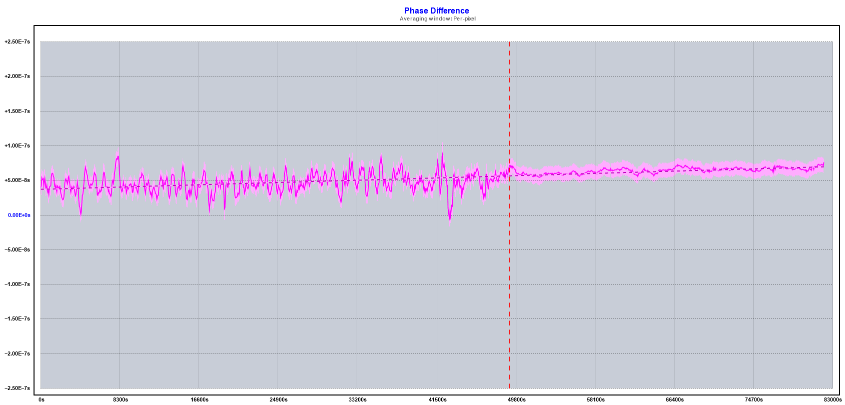
A little while later, I decided to rerun my measurements to try to see what exactly is drifting. For all these measurements, the reference was taken directly from the AHM, not through the distribution amp. Long story short - I covered the bench loosely with a plastic sheet, to minimize the direct airflow from the A/C. The red trace is PLO #1 v AHM, where the oscillator is inside a plastic box. The gold trace is the oscillator inside a plastic box, with the plastic sheet covering the bench. The blue trace has the plastic sheet in place, and the oscillator wrapped in several layers of bubblewrap. The bubblewrap had some effect, but only a few picoseconds. The plastic sheet had a surprisingly large effect.
Lesson learned. Airflow matters.
25.08.2017: Long(ish) term monitoring of maser stability using PPP
I finally got around to building another house of cards of scripts and programs to process daily RINEX-files from the Novatel OEMV3 with gLAB, and create a weekly plot. Quite a few bits and pieces needed gluing together, but in the end it was relatively painless. The Novatel data collection and conversion-utilities are not very stable on Windows 10, so I had to roll my own. I also needed to deal with the Day Boundary Discontinuity, but it was pretty simple to use the Median Absolute Deviation in frequency to identify and remove large outliers between the daily batches. The data quality will not be 100%, but given that the purpose of the plot is to give me a quick "all-is-well", it will do nicely. Any anomalies will have to be investigated further using manual methods, of course. The plot will be updated automatically once a day, but gLAB occasionally inexplicably choke on my RINEX-files, so I will have to chase down that at some point.
Update 14.09.2017
I've tinkered with the setup a little bit, so there are now weekly plots generated for both the Novatel OEMV-3 and the Trimble NetRS. I'm having trouble getting gLAB to correctly process observation from the NetRS when a mix of L2P and L2C are present in the RINEX-file, so for now it is only tracking L2P.
08.06.2017: More PPP results
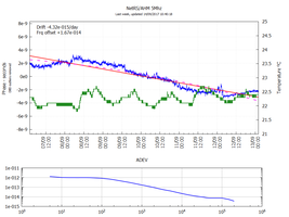
I recently got a GPS L1/L2 antenna splitter, so I can finally run several (L1/L2) receivers in parallel on the same Leica AT502 antenna. Currently I am collecting RINEX data from a Trimble NetRS driven by the maser 5MHz signal doubled up to 10MHz, and a Novatel OEMV3 L1L2L5 GPS+GLONASS driven by the 5MHz signal directly. Today I processed yesterdays data with NrCAN PPP, and imported the clock residuals to TimeLab. Results on the left. The first two hours of data has been deleted - the online version of NrCAN PPP only process data forward, so the first couple of hours are pretty noisy. I also imported the temperature log from the lab, 1 ns corresponds to 1 degree celsius. Nowhere near the .1°C temperature stability the maser "wants", but not too shabby either. Yesterday was overcast which helped - when the sun is shining the temperature varies a bit more.
The results are interesting - and pretty similar. The receivers are not completely comparable - the NetRS is configured to track L2P(Y), the OEMV3 tracks L2C when available. The elevation mask is also different. There are a couple of minutes of missing data in the Novatel-plot; I removed the phase-jump in TimeLab so the data is at least visually comparable. Not "science-quality", obviously, but good enough to give some confidence in the overall setup. BTW, I "tickled" the maser synthesizer at about 40k seconds, a few parts to the -14th, but it really does stand out. Clearly the resolution of this method for measuring frequency is pretty dang good!
For good measure, here is also a plot showing a Ublox 6T hooked up to the same antenna compared to the NetRS PPP clock residuals (collected at the same time) - the PPS of the Ublox is driving the start input on a PM6681 TIC, the stop input is driven by the maser 5MHz signal. Sawtooth correction applied in software. Some difference!
24.05.2017: Aircon (finally) in place
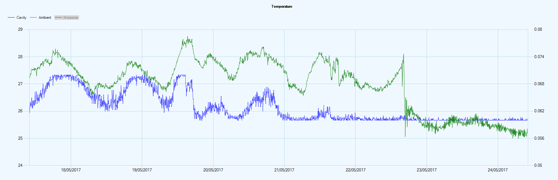
I finally got around to installing airconditioning in the lab. It's been running for a couple of days, and seems to keep the temperature within around 1°C, which is about as good as I hoped for. The temperature coefficient of the hydrogen maser is in the low e-14/C, so actually measuring any instability due to this temperature fluctuation is quite another matter.. I am making progress on using geodetic GPS and PPP postprocessing to reveal the clock residuals, it will be interesting to see if anything shows up. More to come on that front in due time.
16.05.2017: First PPP results!

I got all the bits and pieces collected to do Precise Point Positioning with a "geodetic GPS receiver". The receiver is a Trimble NetRS, which in addition to the required external reference input, also conveniently has an ethernet connection. It can log observables internally in BINEX format, downloadable through FTP. Teqc.exe can read BINEX-files natively, which eases the conversion to RINEX. Uploading the daily RINEX-files to NrCAN PPP gives a surprisingly nice report, including the clock residuals. Seems the maser is a bit off frequency, about 10 ns/day.
All in all a surprisingly painless exercise, although I am sure it will quickly get complicated again. In this case I suspect "ease" is roughly equivalent to "ignorance"..
11.02.2017: Permanent antenna mounted
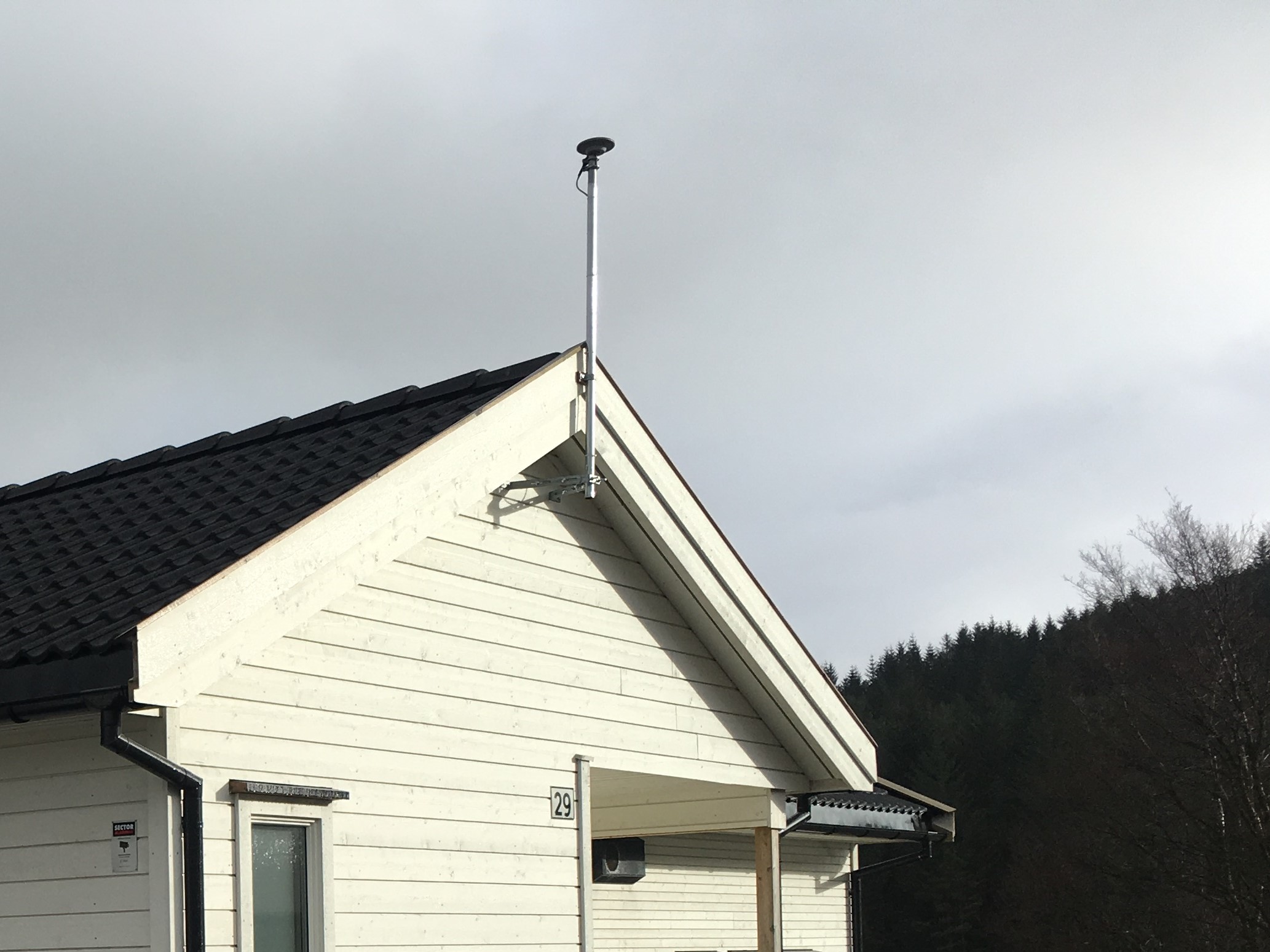
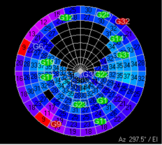
I got at least one antenna permanently mounted in a good position. There are some obstructions up to 25 degrees or so to the north-west, but most of the sky and horizon is pretty much clear. I do have an old MicroPulse L1/L2 choke-ring antenna that will also need to go up, but I need to order a cable for it. Not looking forward to visiting the attic yet again..
27.01.2017: Monitoring system in place
I've put in place the (semi)permanent maser frequency monitoring system. A Fluke PM6681 measures the phase difference between a GPS PPS and the 5 MHz signal from the maser. I swapped out the patch-antenna with a Leica AT-502 GPS antenna. This is a dual frequency antenna, and I was worried that the extra "noise" as seen from a single frequency receiver might be an issue, but based on the results I think not. It is always possible I could shave off a nanosecond or two of wander with a different antenna, but I doubt it would make any difference what so ever. The antenna is still not permanently installed - I spent last night crawling around the rafters in the ceiling - not a pleasant experience! 40 cm of glass wool insulation everywhere, nothing visible to step on, and cramped as ****. So I was not able to run the cables. It is doable, but I need to re-trink where I mount the antennas. I'll get back up there to finish up, but not today. The antenna is still in my lab, now on top of a shelf with no metal close by. A better location than before, at least. With this antenna setup, the U-blox reports a mean 3D standard deviation on its survey location of 63 cm after a couple of hours of surveying, which I think is "good enough" - at least for my initial tests. Contrast to the previous setup, where the deviation was 15 meters. I will do a longer survey over the next couple of days.
The software to fetch TI readings from the PM6681, and read/parse sawtooth corrections from the U-blox receiver was surprisingly simple, done in a couple of hours. There is absolutely no attempt to detect and handle errors gracefully, so I expect it to crash with some regularity. Error-handling will be put in place then - I prefer to just let my software fail, which lets me handle errors that actually occur, rather than try to address anything that could potentially fail. I've never been able to think of everything up front anyway - and some times handling errors can actually mask what really went wrong.
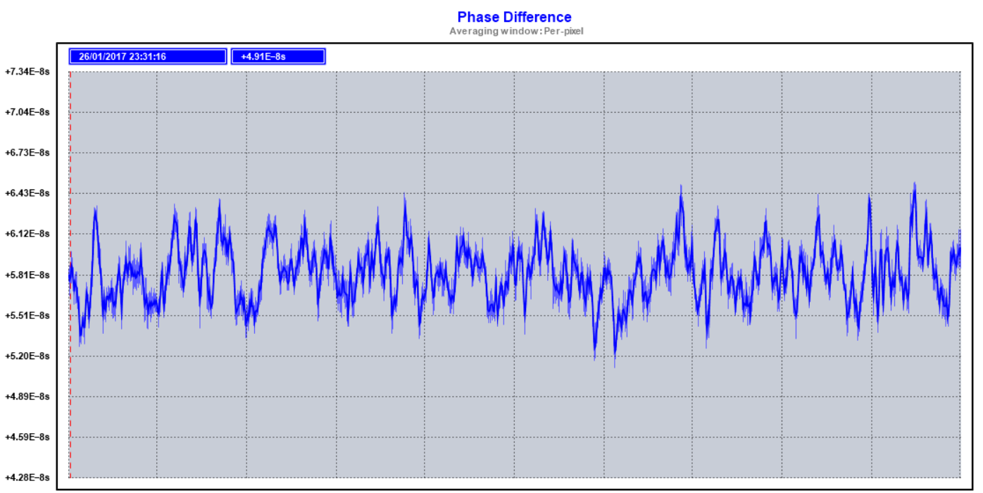
As to results, see graph on the right. It seems I've got about 12-15 ns wander over the few hours I've run it, which should be acceptable for my needs. The slope is currently 2.4e-13 - and given enough time, I might be able to see the drift of the maser. (Unless it is all lost in the noise created by my temperature problem). A plot updated every hour (until it breaks) is here
So, permanent antenna-location aside, the monitoring system is operational and seems to perform reasonably well for what it is.
Update 30.01.2017
I've spent more time with gnuplot than the rest of this project put together several times over. I've finally wrangled it into doing what I want, and there are now daily, weekly and monthly plots generated. Daily and weekly updates every hour, monthly updates at 1 AM. Now to wait for the data to come in...
Update 20.04.2018
The PPP-solutions (see post 25.08.2017) has been running flawlessly for months, so I've decided to stop the PPS measurements.
23.01.2017: Setting the AHM frequency against GPS PPS
EFOS-3 lost power some time during shipping, consequently the synthesizer have been set to the default setting - which may be a bit off in frequency. I primarily use the maser as a reference to measure stablility, so the actual frequency does not really matter. Still, I figured I might try to get it roughly on frequency as well.
The proper way to do this is to use a dual frequency "geodetic" GPS receiver, collect observables for a month or so, apply corrections to satellite orbits and clock residuals, then solve for time with the Precise Point Positioning algorithm. This is still the long(ish) term goal, but I have yet to set up proper GPS antennas and work out all the details.
To get a rough indication of the maser frequency, I set up a U-Blox LEA-6T timing receiver with a silly little no-name patch antenna, unceremoniously placed on my desk. As I have yet to get a decent position fix of my desk, the receiver was not run in position hold mode, the thinking being that it would all average out in the end. The receiver is sensitive enough to get a reasonable sky view anyway, with typically 8-11 satellites tracked. The PPS from the receiver goes to channel 1 on a Keysight 53230A, the 5 MHz signal from the maser goes to channel 2, and a Time Interval measurement is set up. Data is collected with TimeLab. The 20 ps resolution of this counter is overkill for this application, but I chose to use this rather than one of my other counters for the simple reason that it has ethernet connectivity - and I have yet to install NI 488.2 et al on the new lab computer.
When time permits, I plan to set up a permanent monitoring system using a Phillips/Fluke PM6681 or an HP 5334B, and perhaps also implement saw-tooth correction - mostly because it might be interesting. Given the timescales involved here, I doubt saw-tooth correction will make much difference. By keeping a running average of the PPS - 5 MHz phase over several days I should get a reasonable indication that the maser is stable on longer time scales. Perhaps even allowing me to quantify cavity drift with usable precision.
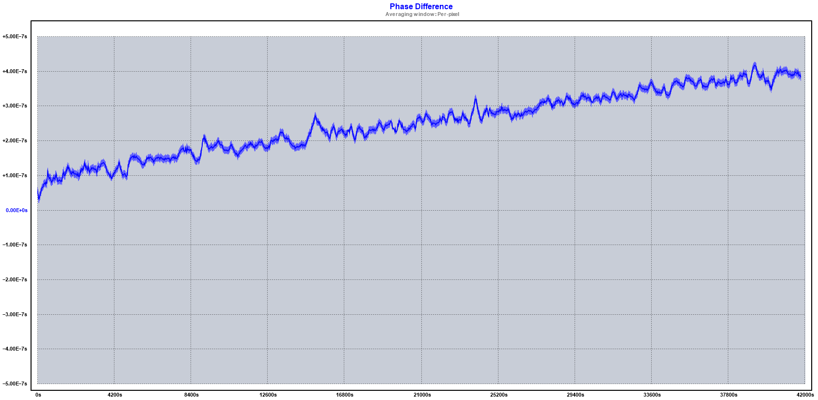
A single frequency GPS PPS can be expected to wander all over the place in the short term, but in the longer term it is very precise. Ionospheric delay being perhaps the prime reason for this wander, but the GPS satellites as they appear in the sky above the antenna can shift the PPS with several nanoseconds - add to this satelllite clock drift, multipath reflections, attenuation, solar flares, antenna type and placement, cables, biases in the receiver, etc etc. The only thing about GPS PPS stability I've been able to ascertain with any degree of certainty is that this is one big can of worms. Also, as can be clearly seen in the temperature telemetry plot, the temperature in my lab is far from stable; a major issue that needs adressing at some point. By chance, the temperature in the lab when this measurement was taken was stable within about 1°C. Exactly how long one would have to wait for these effects to average out I am not really sure, but certainly more than 24 hours. Even with all this uncertainty, 11 hours in I decided that the trend was clear enough with a slope of 7.38e-12 that I would make the first tentative adjustment of the synthesizer, going from the nominal 5.75168900 kHz to 5.75167900 kHz, a step in frequency of -7e-12.
Some 12 hours later, the phase view in TimeLab looks much better. The slope is a much more comforting 2.59e-13, which gives me some confidence that the setup is sound at the timescales observed. The actual clocks on board the GPS satellites are stable to about 1e-13 over a period of one day, and with all the other uncertainties already mentioned, this result is probably as good as I can hope for. I would like to do even better, but I do not think this setup is appropriate for much better precision. Or rather, I would have to average for a lot longer. Although, at some point the time over which I am averaging meets the drift of the maser, and then I think PPP with corrections is the only way forward. Time to start putting together some software and get proper antennas in place..
Update 24.01.17
I left the measurement running for another 12 hours, but switched the receiver in to position hold mode. The position is not very accurate, but I thought the effects on the phase view was interesting. If you ever wondered if position hold really makes any difference for a GPSDO, I think the answer is "yes".
17.01.2017: An unexpected link between U57 and synthesizer setting
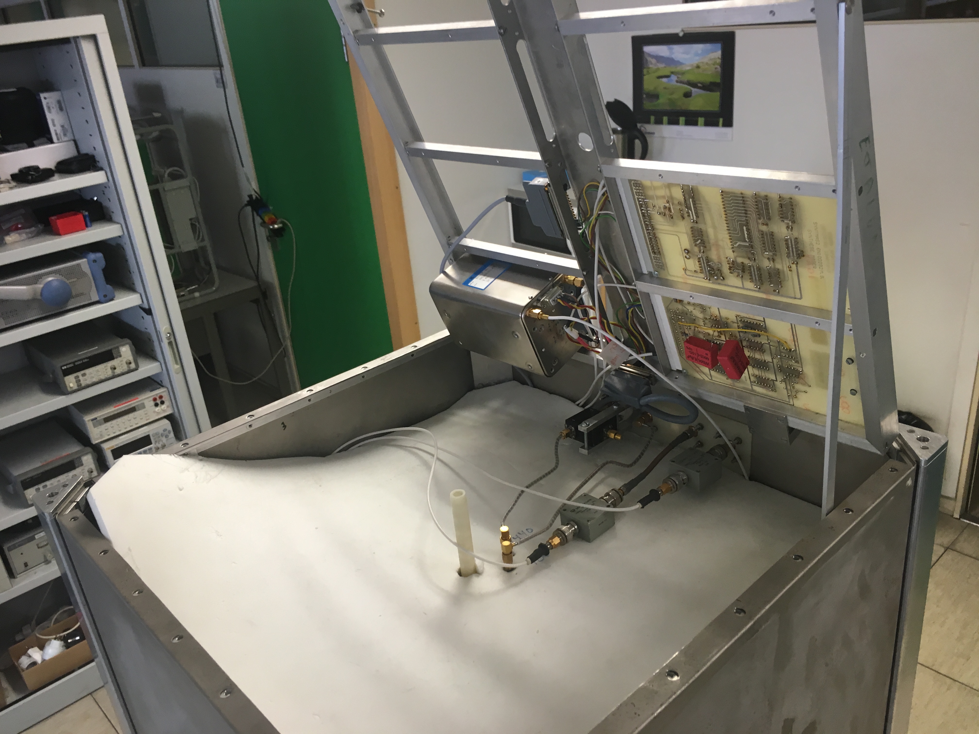
I finally got around to setting up a more permanent logging on EFOS-3. Up to now, I have been using a laptop with a USB to serial adapter. This arrangement was not really satisfactory, since it required the laptop to be located close to the maser, and the USB-cable formed a nice trip-wire. So I replaced it with a two-port Digi PortServer TS MEI ethernet to serial, and got the cables tucked away nicely. This also allows me to use both RS-232 ports on the maser; one port is dedicated to logging telemetry-data every 10 seconds, but the other can be used for ad-hoc communication. Granted, there's not a whole lot of querying to be done, the functionality of the maser monitoring card is limited to sending telemetry-data or reading/setting the synthesizer.
Still, this gave me the motivation to finally cobble together a program to handle the synthesizer, which allows for fine tuning the maser frequency. Oscilloquartz did ship a program that does this, Monit7, but it is an old DOS-program that is flaky at best, and only sometimes play nicely with USB-adapters. The protocol is pretty trivial, so I wrote a small program in C# to replicate the functionality. Not much to it, for those playing along at home the protocol is described in this document.
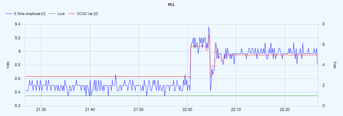
When I was playing around with the program, it struck me that I might abuse the synthesizer setting to run a test I have been meaning to do. The phase noise on EFOS-3 is pretty bad (at least compared to the Oscilloquartz BVA LO), and I had this hypothesis that it might be related to the PLL and tuning voltage. The manual for EFOS-2 states that the OCXO tuning-voltage should be kept around 5 volts, and the oscillator should be adjusted if the EFC voltage is more than 1v off. On EFOS-3, the EFC voltage sits right around 3 volts. Rather than pop the top off the maser and ajust the OCXO, I figured I could adjust the synthesizer setting to bring the tuning-voltage up to 5 volts. This worked like a charm, but as can be seen in the picture, it also had the completely (to me) unexpected result of also increasing the 5.751Khz (U57A) signal! This signal is supposed to be directly proportional to the signal coming out of the cavity, and is an important indicator of the overall health of the maser. I do not see how the synthesizer-setting can influence the signal strengt coming from the cavity..
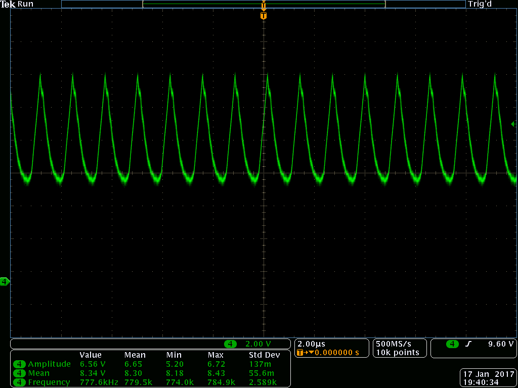
In addition to being available via RS-232, the 5.751 Khz signal is brought out to a dedicated SMA on the front panel of the maser, so it can be measured more precisely than the internal 8-bit converter. I've looked at U57A before, since it is not very stable. Left, a scope screenshot. The frequency of the wave-form is around 775 kHz. As far as I can gleam from the schematics, the signal should simply be a rectified 5.751 Khz sinewave, so it should not look like that.. There is a section in the manual on troubleshooting noise on U57A, but I have not got around to it yet.
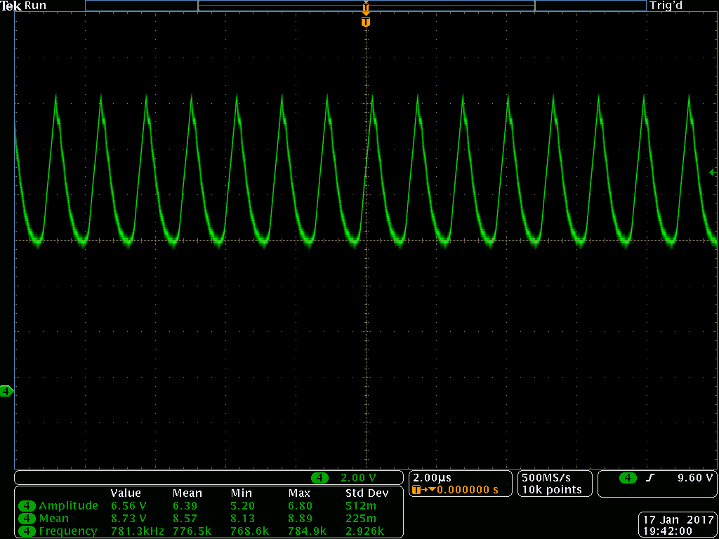
The mystery only deepens when looking at the scope when the tuning-voltage is brought to 5v. Although the maser reports about .5v increased signal, the increase in mean value reported by the scope is more like .2 to .3v.
I do not currently understand how this all comes together, but I will try to work it out. Any ideas or hints would be welcome!